 My wife and I decided we wanted to make clocks as Christmas gifts for our family. I have some woodworking knowledge and access to a laser cutter so I thought the project would have a high likelihood of success.

3D CAD model of clock
I started by creating a 3D CAD model of the clock. This helped determine overall size, placement of numbers, and font.
I went to Crosscut Hardwoods in the SODO neighborhood of Seattle. After contemplating many different types of wood I settled on a rough cut piece of cherry.
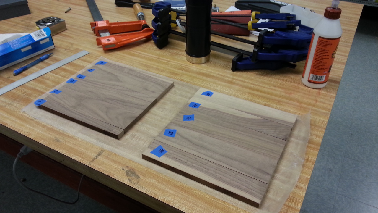
Boards laid out in the desired configuration with labels.
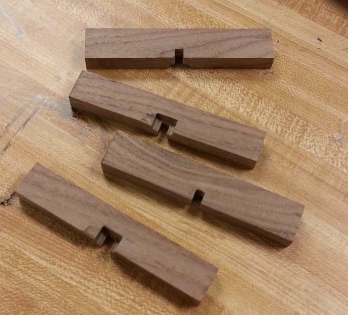
I cut the pieces to size and cleaned up the ends and sides with a board jointer. The faces were intentionally left rough as that was the desired aesthetic. The pieces were laid out next to one another to see which configurations would give the most interesting layout. The pieces were labeled so if the decided upon order got messed up we could get it back to how we wanted it.
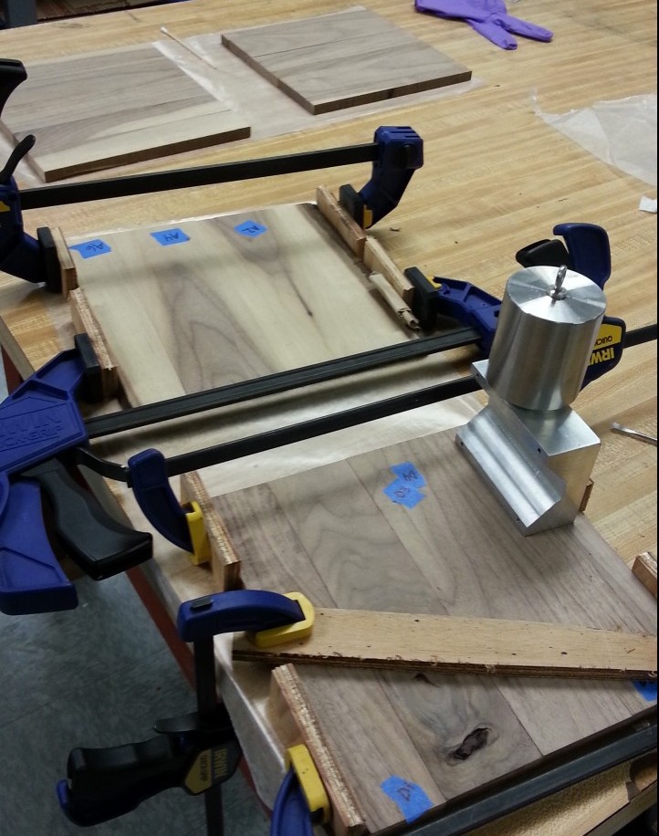
Panels glued and clamped
The boards were then glued together. I originally intended to only glue one piece at a time. Lack of time, however, forced me to glue an entire panel together at once. Clamps were placed against the length of the panel in the direction of the glue joint. The panels were also clamped to the table surface to ensure they remained flat.
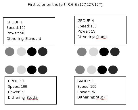
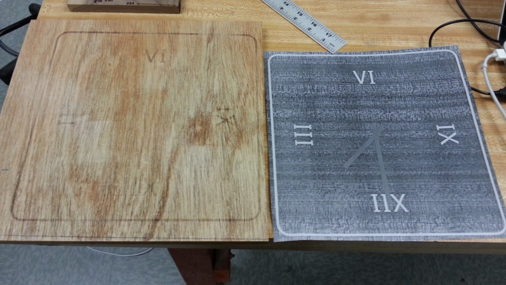
The panels were now ready to etch but I still needed to finalize the laser settings. I did a couple of trials. The first showed how different power and dithering settings affected four different gray scale colors. This was etched onto a representative wood piece. The second test was to print the clock face on an similarly sized piece of wood and ensure the laser head was aligned and focused correctly.
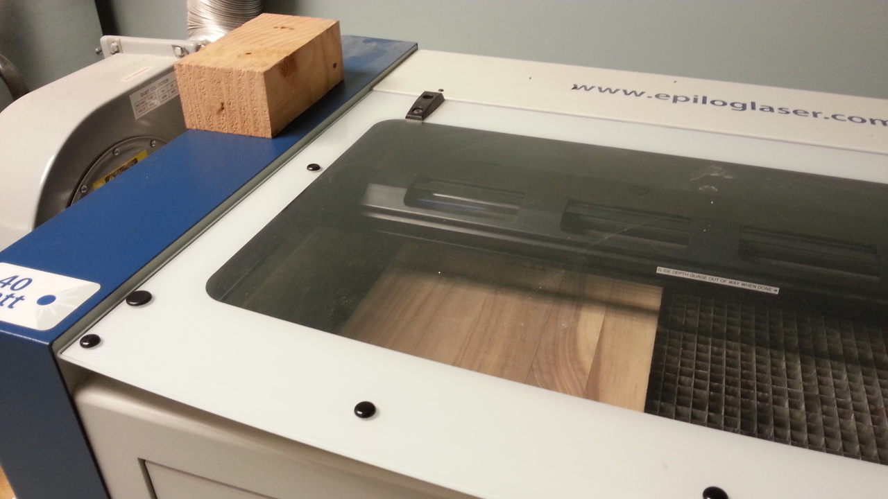
Laser etching the clock faces
The four clock faces were then laser etched using an Epilog Zing 24.
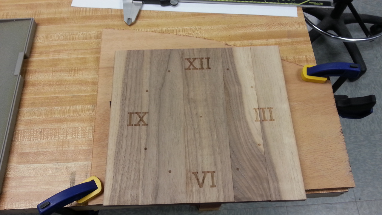
A freshly etched clock face
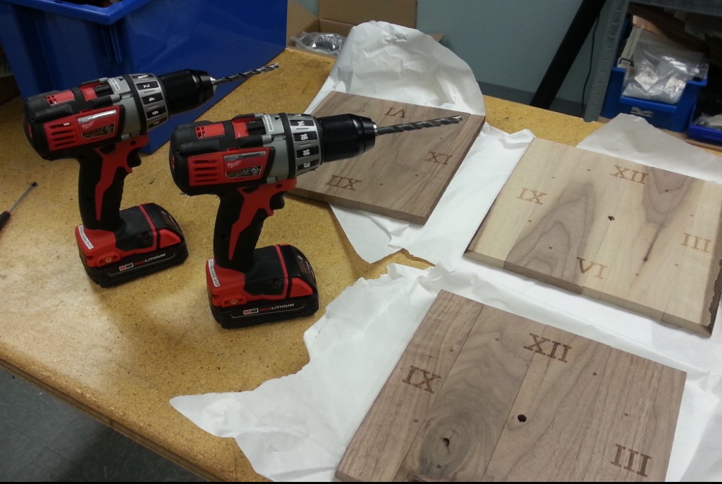 The holes for the clock spindle were then made in the face. Two different drill sizes were used to reduce the amount of splintering and tearing that would normally be caused by a large drill bit

Machining the clock mechanism pocket
Now that the spindle hole location was finalized, the pocket for the clock mechanism could be machined. A lot of clocks will just let the clock mechanism hang off the back causing the clock not to lie flush against the wall. I had enough material thickness so decided it would be a nice feature to add.
Clock hangers
I clamped each panel to the mill, centering the bit on the spindle hole. Since I was worried about damage to the front face, I placed a few strips of foam rubber between the mill plate and the clock face.
I also was able to use the mill to create the clock hanging mechanism. This was glued to the back of the clock panel and clamped in place while the glue dried.
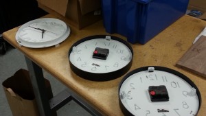 Several wall clocks were cheaply obtained from the nearby Target. They were diassembled and the internal mechanisms were removed. The removed parts were then added to the existing clock panels.
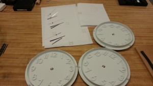
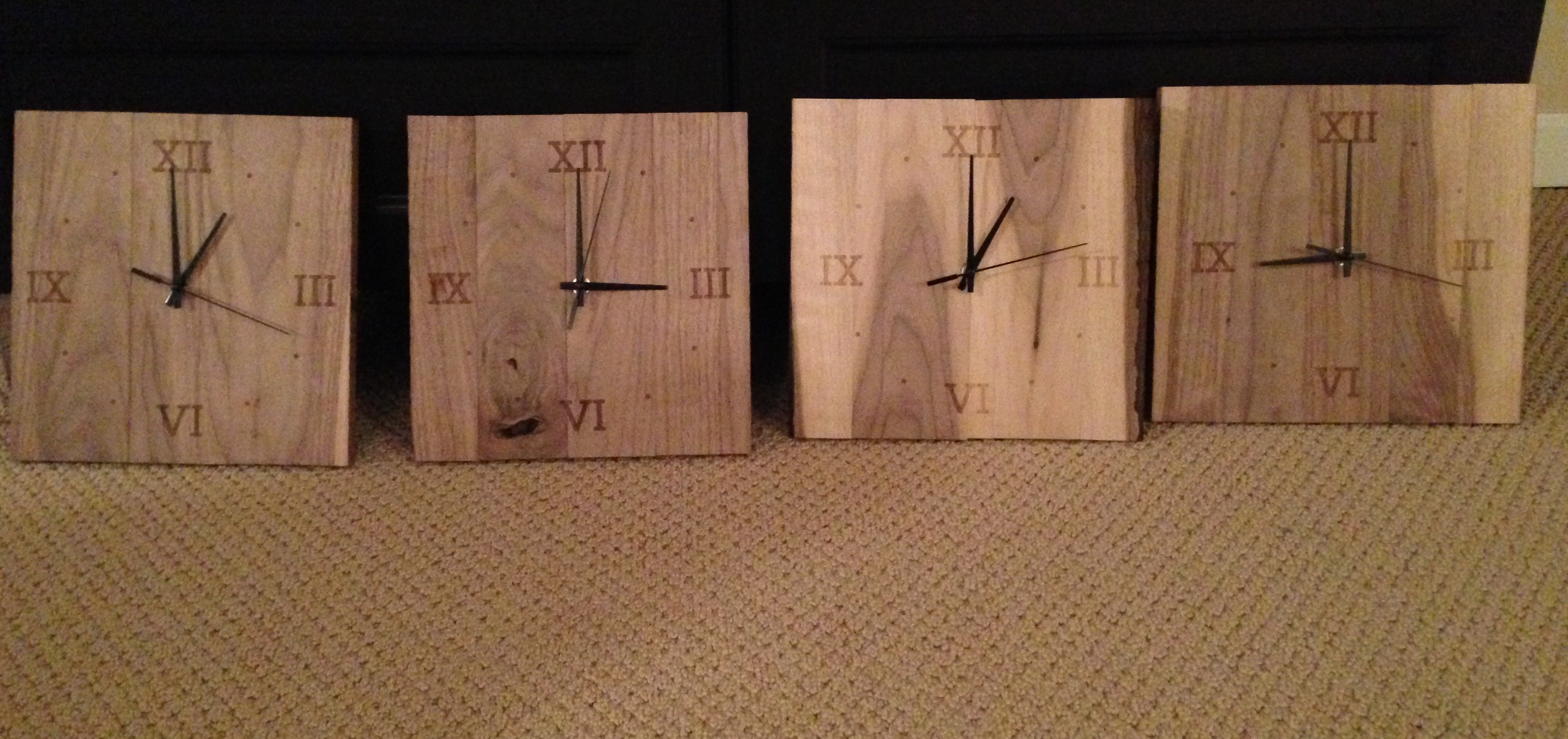
This completed the assembly. Here is the final view of all four clocks.